The proposed development at Noida sector 94 near Maha Maya Flyover consists of two tower blocks, a service apartment and Hotel building. Both the tower blocks houses 3 -levels of basement car park, ground floor, two levels of podium above ground. The service apartment rectangular on plan consists of 3B+G+2 Service+39 Typ.=45 Floors and Hotel building shall be 3B+G+32 Service+32 Typ.= 38 Floors.
Aecom has been engaged to provide the Civil & Structural and MEP design services for the above development. By the time Aecom-Spectral is on board the concept design was laid out by other consultant. Since the previous design information was not made available except the concept drawings, AECOM chosen to produce and develop it’s very own analysis and design from the beginning.
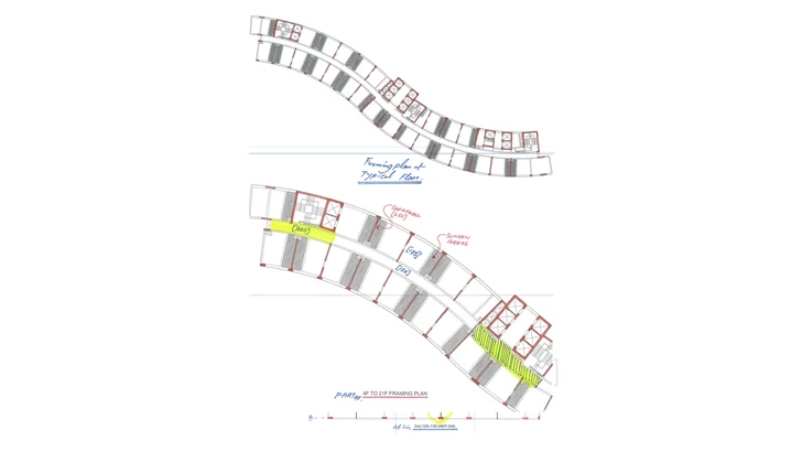
Various structural options were explored for the hotel and service apartment buildings. For Hotel building considering the floor shape and arrangement of guest rooms and sunken toilet areas a conventional beam slab system is recommended however for service apartment building the following two options are presented,
- Two-way Beam Slab
- Flat Slab
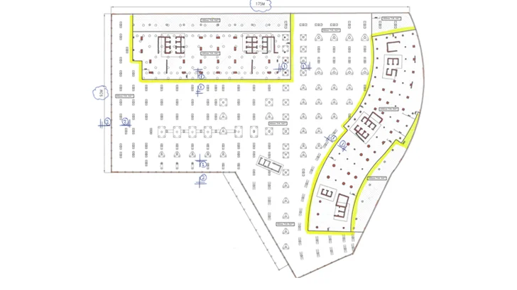
Based on design development workshop between architects, Services engineers, and client’s representatives a structural framing plans at typical floors are established. The proposed structural system was efficient for the proposed architectural layout due to its similarity of layouts at upper levels. In this system no down-stand beam crosses the corridor therefore it facilitated to run the mechanical/electrical services with ease and minimize the impact on floor height.
Considering the architectural design intent, the column locations have been chosen at reasonable spans to arrive at minimum slab thickness. The column sizes and slab thicknesses are chosen considering the gravity and lateral loads and the punching shear stress requirements. The column thicknesses and orientation are adapted to suit with the proposed architectural layouts at typical floors and the car parking arrangement and driveways in basement floors and at ground floor.
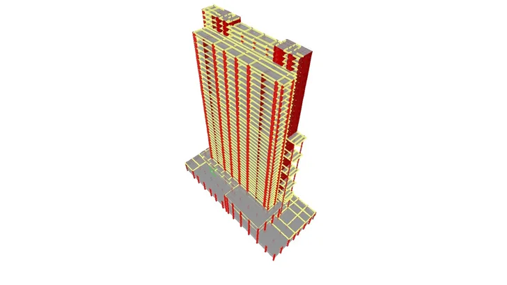
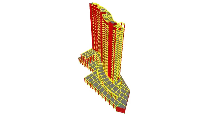
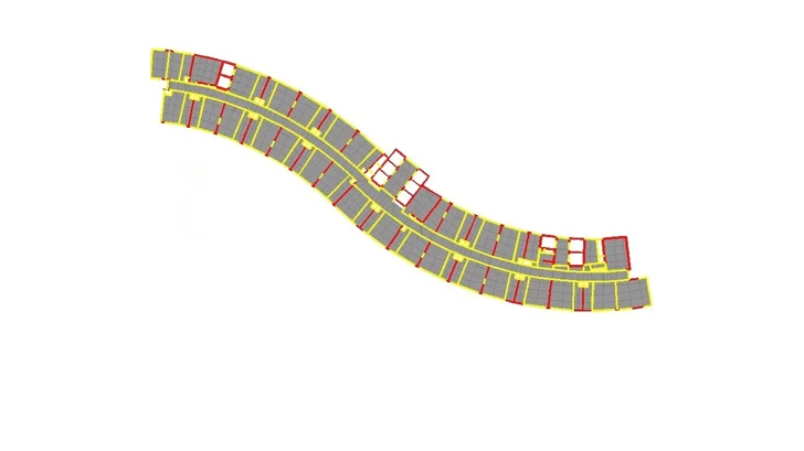
The structural stability of the service apartment potentially provided by stair/Lift core walls in each principal axis. Since the building stiffness along shorter direction is inadequate therefore an additional shear wall along required direction are introduced to resist the lateral loads induce out of wind and seismic loads in shorter (Y-axis) direction.
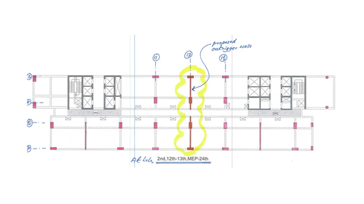
An initial 3-Dimensional analysis using Etabs version 9.7 has been carried to estimate the proportions of shear walls and columns. The above analysis is carried out to support the design gravity and lateral loads. On basis of initial analysis run it is concluded that an additional outriggers are required to add building stiffness in either directions. The proposed outriggers are discussed with architects and agreed upon to introduce outrigger walls to meet building serviceability acceptance criteria. The introduction of concrete shear walls locations was studied carefully without damaging the architectural intent and MEP requirements, therefore the concrete shear walls at MEP service floors (L3 and L24) with appropriate door openings, L12, L13 along vertical grid line 11, 13 and 15 are provided. Beside the above shear walls the shear wall along the grid line S connecting the lift cores at each sides are also included to improve the stiffness in X-direction.
project details
- Client : Vision Town Planners Pvt Ltd.
- Year of Design/Const : 2012 - 2013
- No of Floors : 3B+G+2service+39 = 45 Slabs
- Architect : Design Plus Architect (DPA), Modi Mills, Okhal Phase III, New Delhi.
-
Structural Consultant
:
AECOM India Limited
Structural design led by Abdul Raoof - Project Status : Under Construction
- Project Location : Maha Maya fly-Over Noida, India